A guide for setting up safety of a work cell equipped with a Yaskawa SRCI robot.
For an SRCI system, a special safety setup is required to ensure that the robot can be operated safely, also in service scenarios where the operator is inside the work cell. When using SRCI commands, the robot controller is in REMOTEmode, meaning that the native speed limit for TEACH mode is not available.
In this guide, we will create the “safe limited speed” for SRCI using the Functional Safety Unit’s (FSU) speed limit function. Also, we will use an additional key switch for selecting the “point of control”. This will allow us to cover not only SRCI scenarios, but also scenarios where the native robot pendant is used (e.g. by Yaskawa service technicians).
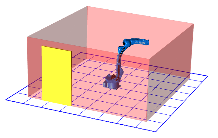
System layout
For this guide we have chosen a simple but common system layout. The robot is placed inside a fenced work cell and the operator can access the dangerous area through a service door. Thanks to the implemented safety measures, the operator is able to move the robot slowly while being in the dangerous area.
Components
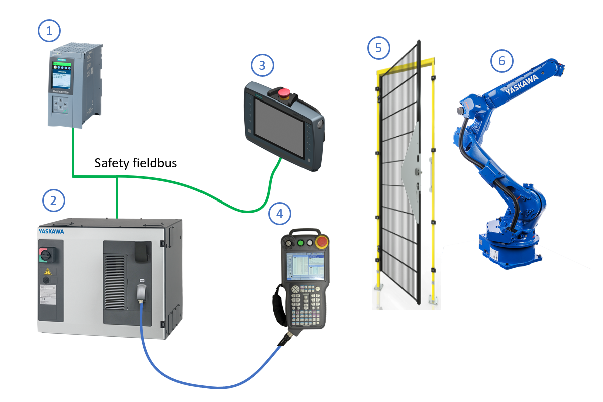
Safety PLC
The PLC (e.g. Siemens 1516F-3PN) not only runs the user program (controlling the robot using SRCI) but also the safety program (handling the safety of the work cell).Robot controller
The controller (e.g. YRC1000) with SRCI option comes with the FSU option. In this example, we use the additional safety fieldbus option (e.g. PROFIsafe) to save on safety wiring.The safety fieldbus option is not available for the YRC1000micro controller. In that case, regular 2-channel safety wiring will be used (see robot manual).Mobile HMI
The mobile HMI (e.g. Siemens KTP900F) is used as the operator panel for the work cell – which includes controlling the robot using SRCI – in both automatic (production) and manual (service) scenarios. It needs the following safety features:- E-stop
- 3-position enable switch
Robot pendant
On a SRCI system, the standard Yaskawa programming pendant is only required during first time commissioning (e.g. FSU setup) and maybe later during robot maintenance by Yaskawa service technicians.The Yaskawa robot pendant can be replaced by a special dummy connector.Service door
The door switch is connected to a PLC safety input.Although not covered in this example, it is advised to use a door switch with built-in locking device. This allows a more sophisticated way of stopping the robot cycle (e.g. at a defined position), compared to just opening the door at any time.Manipulator
The robot (e.g. GP20) controlled by the PLC using SRCI.
Considerations
For the safety design of the Yaskawa SRCI system, we need to consider various aspects.
Single point of control
As there are two operating panels in the system, we need to make sure that it is very clear which one is in use, and interlock it so that a single point of control is guaranteed.
From control point of view, this is already secured by the fact that SRCI only works with the robot controller in REMOTE mode whereas robot pendant operation is only possible in TEACH or PLAY mode.
From safety point of view, it is a different story. In case of robot pendant operation, the native safety functions need to be used. In case of SRCI operation, it will use the safety mechanisms we create in this guide. These two modes need to be interlocked in the safety PLC. We will do this using an additional key switch which is connected to a safety input.
With this switch, the operator will choose between operation by SRCI (using the mobile HMI) or by robot pendant.
Stop behavior
For the SRCI safety setup, we will stay as close as possible to the robot controller’s native stop behavior, which is described in below stop category table from the YRC1000 instructions manual:
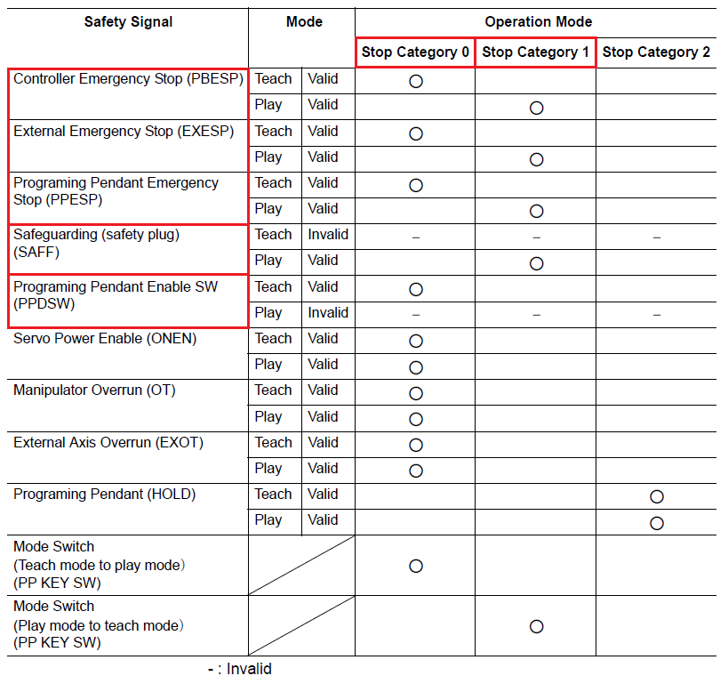
This table tells us that the native stop behavior is:
- Making sure that the robot stops immediately (cat-0) where needed (e.g. operator in dangerous area)
- Stopping normally (cat-1) in all other cases
The latter prevents the manipulator from extensive wear when e.g. the service door is opened frequently while moving at high speed.
Implementation
To implement the safety for SRCI, we will use the following robot signals:
| Direction | Robot signal | Comment | Purpose |
|---|---|---|---|
| PLC to robot | S-EXESP | External E-stop | Execute emergency stop |
| PLC to robot | S-SAFF | Safety fence | Pass status of safety fence (service door) |
| PLC to robot | SVOFF CAT0 | Category 0 stop | Execute immediate stop |
| robot to PLC | PPESP | Pendant E-stop | Integrate robot controller’s E-stop button into the PLC’s E-stop circuit |
Additionally, we will create a speed limit configuration in the FSU with a setting
of 250 mm/s for the safe limited speed.
This will be used when running SRCI motions while being in the dangerous area.
Setup
Safety fieldbus
- Adjust settings and IO address for PROFIsafe device:
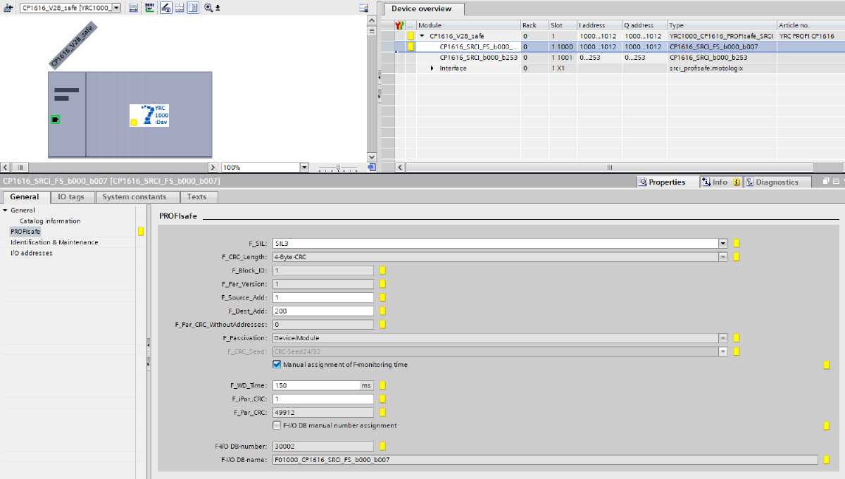
CP1616 PROFIsafe device settings.
IO
Buttons and switches
This example uses the following safety switches/buttons which are connected to PLC safety inputs:
- Key switch for selecting point of control (PLC/robot pendant)
- Safety door switch
- Emergency stop button
- 3-position enabling switch

PLC to robot
PLC variables
- Create safety data type (size: 64 BOOL):

Data type for safety fieldbus data to robot. - Create PLC tag and map to safety fieldbus:

PLC tag for safety fieldbus data to robot.
Robot controller signals
Create SFBIN signals: SAFETY FUNC. » SAFETY SIG. BOARD ALLOC » SIGNAL CHG » SFBIN
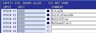
SFBIN input signals in the robot controller. SFBIN = safety fieldbus inputs
Robot to PLC
PLC variables
Create safety data type (size: 64 BOOL):

Data type for safety fieldbus data from robot. Create PLC tag and map to safety fieldbus:

PLC tag for safety fieldbus data from robot. For simplicity, we will not evaluate the safety limited speed feedback signal.
Robot controller signals
Create SFBOUT signals: SAFETY FUNC. » SAFETY SIG. BOARD ALLOC » SIGNAL CHG » SFBOUT

SFBOUT output signals in the robot controller. SFBOUT = safety fieldbus outputsM-SAFE = for usage inside safety logic circuit
F-SAFE = for usage inside FSU functions
Logic
Robot
safety mode authorization level.Create the safety logic circuit: SAFETY FUNC. » SAFETY LOGIC CIRCUIT

Content of safety logic circuit. Create the safe limited speed: SAFETY FUNC. » SPEED LIMIT
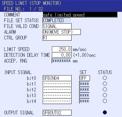
Setup speed limit for creating a safe limited speed.
PLC
Set the time delay which is used for the scenario where the robot should come to a standstill using a normal- instead of immediate stop:

Time delay setting. Create an off-delayed signal for the door switch:

Off-delayed door switch signal. Create the logic for the E-stop signal to the robot. The PLC E-stop circuit and robot pendant (local) E-stop are combined:
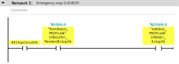
E-stop signal to robot. Create the logic for the safety fence signal to the robot. In case of PLC control, the safety fence signal only drops shortly when opening the door. This will stop the motion with a normal stop.
After the delay, the signal comes back. This is necessary, because the connected
SAFFrobot signal would prevent the robot to run (even with limited speed) in REMOTE mode.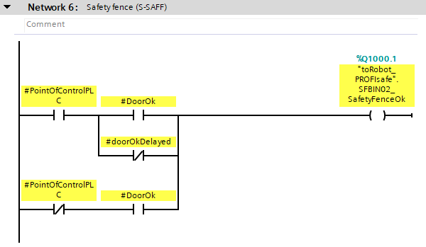
Safety fence signal to robot. Create the logic for the immediate stop signal to the robot. In case of PLC control, the immediate stop signal comes shortly after the door was opened (allowing the robot to stop gently with a normal stop). It is bypassed as long as the 3-position enabling switch is pressed. Also, this immediate stop applies when the E-stop is hit while the door is open.
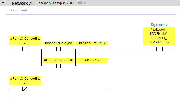
Immediate stop signal to robot. Create the logic for the speed limit signal to the robot. In case of PLC control, the speed limit applies when the door is open.
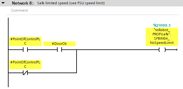
Speed limit signal to robot.
Tests
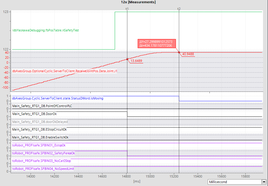
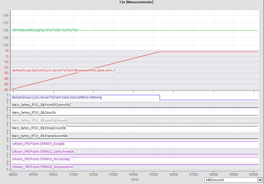
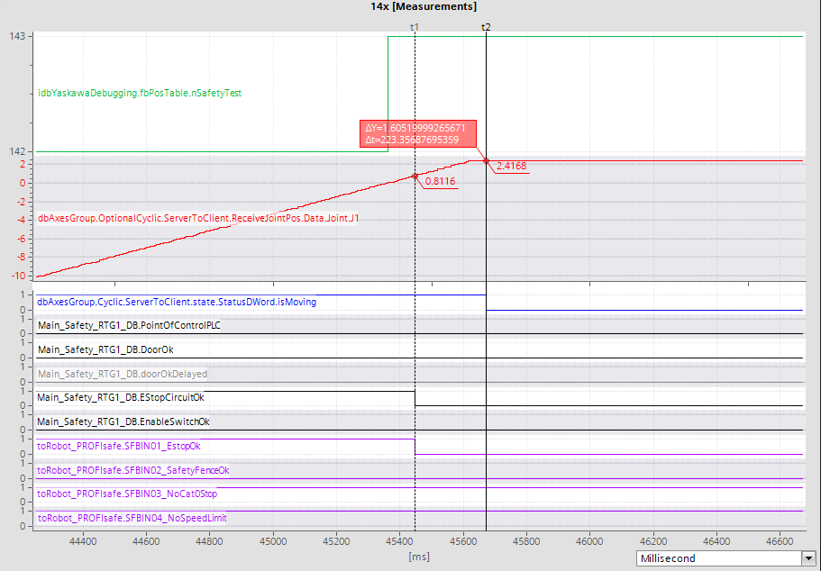
To verify the SRCI safety setup, we have setup a few automated tests. In these tests, a GP12 robot is moving the S-axis back and forth using point-to-point motion with 50% speed. Then, in the middle of the motion, the corresponding safety inputs are triggered, e.g. to simulate the opening of the service door:
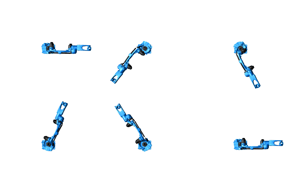
During the test, data is captured using a PLC trace (IO signals) and the optional robot pendant oscilloscope (TCP speed).
With the latter, the TCP speed and the stop type (normal or immediate) can be verified easily. A straight (vertical) line represents an immediate stop (cat-0) whereas an “s-curve” shaped line represents a normal stop (cat-1).
Results
01x
# test conditions
point_of_control: PLC
operator_location: outside cell
stop_cause: E-stop
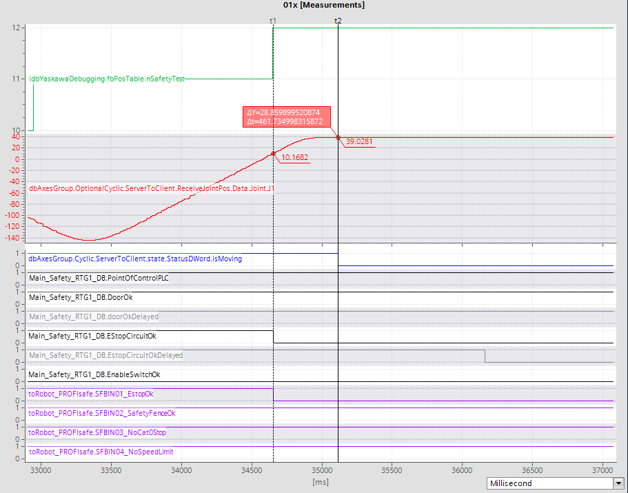
![01x: TCP speed [mm/s] 01x-speed](https://srci.yaskawa.eu/setup-safety/test-cases/01x-speed-web.jpg)
02x
# test conditions
point_of_control: PLC
operator_location: outside cell
stop_cause: opening service door
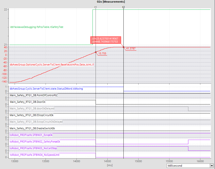
![02x: TCP speed [mm/s] 02x-speed](https://srci.yaskawa.eu/setup-safety/test-cases/02x-speed-web.jpg)
03x
# test conditions
point_of_control: PLC
operator_location: inside cell
stop_cause: enabling switch
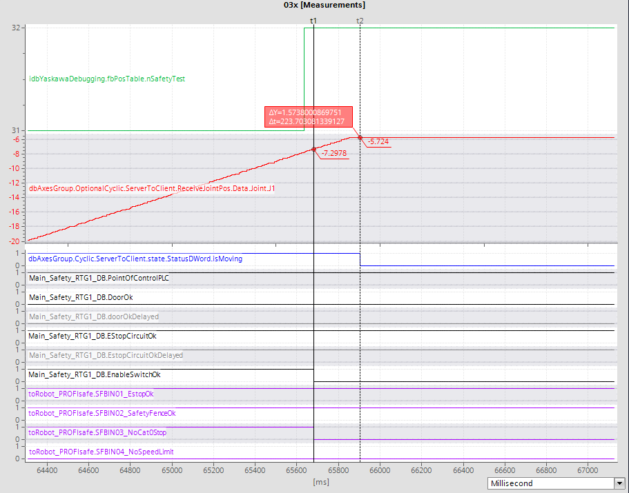
![03x: TCP speed [mm/s] 03x-speed](https://srci.yaskawa.eu/setup-safety/test-cases/03x-speed-web.jpg)
04x
# test conditions
point_of_control: PLC
operator_location: inside cell
stop_cause: E-stop
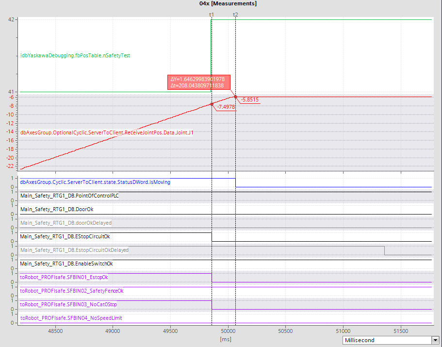
![04x: TCP speed [mm/s] 04x-speed](https://srci.yaskawa.eu/setup-safety/test-cases/04x-speed-web.jpg)
11x
# test conditions
point_of_control: robot pendant
operator_location: outside cell
stop_cause: E-stop
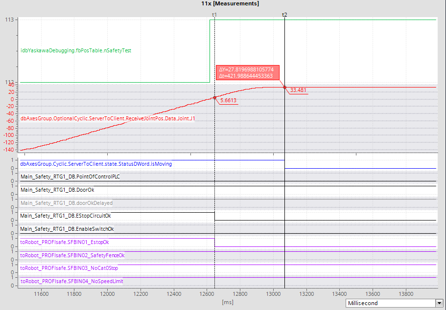
![11x: TCP speed [mm/s] 11x-speed](https://srci.yaskawa.eu/setup-safety/test-cases/11x-speed-web.jpg)
12x
# test conditions
point_of_control: robot pendant
operator_location: outside cell
stop_cause: opening service door
![12x: TCP speed [mm/s] 12x-speed](https://srci.yaskawa.eu/setup-safety/test-cases/12x-speed-web.jpg)
13x
# test conditions
point_of_control: robot pendant
operator_location: inside cell
stop_cause: enabling switch
![13x: TCP speed [mm/s] 13x-speed](https://srci.yaskawa.eu/setup-safety/test-cases/13x-speed-web.jpg)
14x
# test conditions
point_of_control: robot pendant
operator_location: inside cell
stop_cause: E-stop
![14x: TCP speed [mm/s] 14x-speed](https://srci.yaskawa.eu/setup-safety/test-cases/14x-speed-web.jpg)