Fieldbus setup information for SRCI in Siemens TIA portal.
Supported boards
Yaskawa SRCI supports the following PROFINET boards:
| board | data packet (byte) | driver | firmware |
|---|---|---|---|
| CP1616 | 254 | - | v2.8 |
| CP1616 PROFIsafe | 254 (+ 8 PROFIsafe) | - | v2.8 |
| INPACT | 436 | v3.0.30.9 (or newer) | - |
| CIFX | 436 | - | - |
Fieldbus files
Please only use the fieldbus files supplied by Yaskawa Europe.
- Download the latest files using above link
- Unzip the files
- Import the GSD’s into TIA Portal: menu Options » Manage general station description files (GSD)
Setup
CP1616 slave
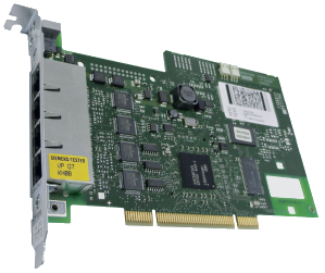
Read more...
GSDML-<version>-#YASKAWA-PreConf_YRC1000_CP1616_standard_SRCI-<date>- Grab the YRC1000_CP1616_standard_SRCI IO-device from the
hardware catalog:

IO device - Assign the IO-controller by clicking on
Not assignedand assigning it to your CPU. - Double click on the robot icon to open the properties
- Adjust the IO addresses to your needs:

IO addressing - Create a data type of 254 byte for the SRCI data:

Data type for SRCI data - Create a PLC tag and map it to the SRCI data:

IO mapping - Connect
fromRobot_SRCI.dataandtoRobot_SRCI.datato yourMC_RobotTask_LRobinstance
CP1616 PROFIsafe slave

Read more...
GSDML-<version>-#YASKAWA-PreConf_YRC1000_CP1616_PROFIsafe_SRCI-<date>Grab the YRC1000_CP1616_PROFIsafe_SRCI IO-device from the hardware catalog:

IO device Assign the IO-controller by clicking on
Not assignedand assigning it to your CPU.Double click on the robot icon to open the properties
Adjust the IO addresses for both the normal- and the safety IO to your needs:

IO addressing Open the PROFIsafe properties: right click on PROFIsafe address entry » properties » PROFIsafe
Adjust the PROFIsafe settings to your needs:
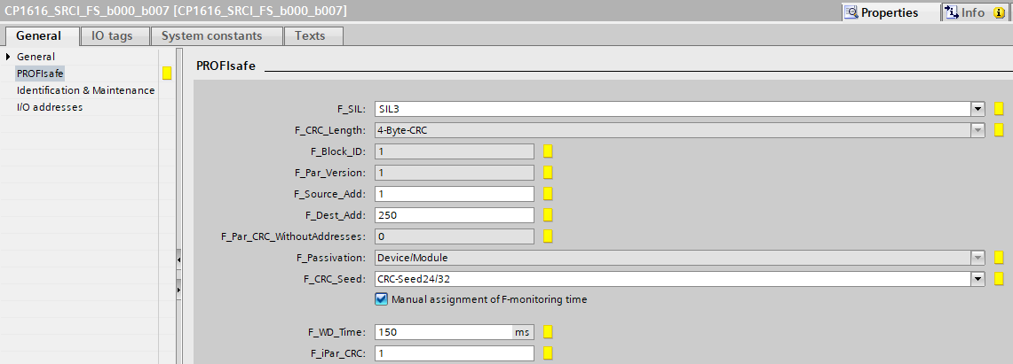
PROFIsafe settings item value F_Dest_Address adjust to your needs F_iPar_CRC 1The value ofF_Dest_Addhas to match the setting in the Robot setupCreate a data type of 254 byte for the SRCI data:

Data type for SRCI data Create a safety data type of 64 booleans for the PROFIsafe data:

Creating a safety data type 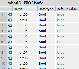
Data type for safety IO By creating separate safety data types per direction, you can name the signals according their assigned function.The safety signals are assigned in the robot controller: Safety Func. » Safety Logic Circuit (refer to the robot manual for more information)Create a PLC tag and map it to the SRCI data:

IO mapping Create a PLC tag and map it to the PROFIsafe data:

PROFIsafe IO mapping Connect
fromRobot_SRCI.dataandtoRobot_SRCI.datato yourMC_RobotTask_LRobinstance
INPACT slave
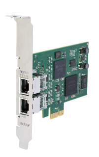
Read more...
GSDML-<version>-HMS_CUSTOM-ABSPRT-<date>- Grab the INPACTpir IO-device from the
hardware catalog:

IO device - Assign the IO-controller by clicking on
Not assignedand assigning it to your CPU. - Double click on the robot icon to open the properties
- Add the
Input/Output 109 dwordsmodule - Adjust the IO addresses to your needs:

IO addressing - Create a data type of 436 byte for the SRCI data:

Data type for SRCI data - Create a PLC tag and map it to the SRCI data:

IO mapping - Connect
fromRobot_SRCI.dataandtoRobot_SRCI.datato yourMC_RobotTask_LRobinstance
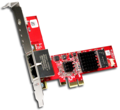
CIFX slave
Read more...
GSDML-<version>-YASKAWA-CIFX-<date>- Grab the Yaskawa CIFX IO-device from the
hardware catalog:

IO device - Assign the IO-controller by clicking on
Not assignedand assigning it to your CPU. - Double click on the robot icon to open the properties
- Add the
Input/Output 436 bytesmodule - Adjust the IO addresses to your needs:

IO addressing - Create a data type of 436 byte for the SRCI data:

Data type for SRCI data - Create a PLC tag and map it to the SRCI data:

IO mapping - Connect
fromRobot_SRCI.dataandtoRobot_SRCI.datato yourMC_RobotTask_LRobinstance